 My youngest son Nigel is a keen RC glider enthusiast. He was keen to try airborne video and adverts in the aeromodelling mags. revealed sources of the licence-free transmitters. We obtained ours by mail order from:
 My youngest son Nigel is a keen RC glider enthusiast. He was keen to try airborne video and adverts in the aeromodelling mags. revealed sources of the licence-free transmitters. We obtained ours by mail order from:
ATC Electronics, 14 Tonbridge Chambers, Pembury Road, Tonbridge Kent, TN9 2HZ
Tel: 01732 355 955
Fax: 01732 355 633
In April 1999 we bought a simple Mono (Black and White) transmitter for 1394MHz (type VTM880). The output is 50mW, which might not seem much, but is adaquate to give a reasonable signal within the line of sight which is essential for control of the glider.
The system contains the following components:
Glider end:
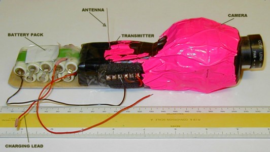
1. VTM880, 12V 120mA input 50mW output, transmitter,wt=20gram
2. Rigid wire monopole antenna, direct from transmitter
3. Camera, power supply via transmitter, 11v 60mA, wt=80grams
4. 12V battery pack, 180mAh NiCds,wt=280grams
5. Overall weight 380grams - make sure the model will carry it!
Ground equipment:
1. Dual dipole and reflector array as antenna - Horn illuminator from the design in the RSGB VHF handbook. Strictly speaking this antenna was designed for 1296MHz and not the 1394MHz used - however it was available and it worked. A design modified for this frequency will be built and should give better results - over longer range.
2. Amstrad SRX200 satellite receiver modified for 12V operation. This unit was purchased at a radio rally for £2 and modified according to the instructions from the BATC mag. CQ-TV - see link elswhere on this site.
3. Sony Mono video Monitor (dual 12V /240V operation)- bought at a rally for £15 - and LCD unit would have been better in sunlight!
4. Car battery used for power.
Tests so far:
1. Ground trials proved that the transmitter worked over slightly more than line of sight when the airborne end was taken for a walk along the road whilst receiving good pictures back at the base. Battery power was falling off fairly rapidly after ten minutes or so not because the batteries were exhausted but because the battery voltage was insufficient to work the camera.
2. After putting another cell in the battery to lengthen the time the camera was operational, a further trial was carried out and this showed that about thirty minutes at least was possible.
3. An airborne trial took place during the summer of 2000 which proved that the system worked well with some provisos:
3a. The monitor was poor in sunlight and required a hood and was best inside the car
3b. The only dropouts in the video occurred for a short time during acrobatics when the antenna was pointed directly away from the receiver. It may be possible to minimize this effect by putting a different antenna on the aircraft but this problem was not serious.
3c. It was hoped to be able to use the video to fly the aircraft but the wide angle lens fitted gave insufficient detail and was in any case pointed downwards rather than towards the front. The video therefore gave little indication of orientation and direction.
Latest camera pod design, shown below - about 230mm long, with camera and transmitter encased in foam and plastic sheeting. The tiny tinned copper wire antenna works surprisingly well.

Overall it proved that the system works. The next test will be a video recording of a flight and we need to build a 230V inverter system for that.
When Maplin were selling off 150W inverter systems for £20 (August 2001), we bought one to run the VCR.
Hopefully a new trial with a video recording will take place when the weather has settled down in August 2002
Last updated 2002 August 5