1. An 800mW PA was obtained from W0EOM via G3PHO who coordinated the UK purchases. The unit was drawn up and flanges and a heatsink designed and machined to suit. The input to the PA is WG22 in copper which can easily be opened out to WG21 internal size by means of a tapered steel tool (the tang of a file suitably modified).
2. The construction was to follow the design of the MK2 10Ghz beacon and be within a water resistant box with the antenna on top. The design would be also following the 10Ghz system by using a mixer at 24Ghz to add the modulation via a DDS derived IF signal.
3. Also following the design of the 10GHz beacon, it was decided to make a slotted waveguide antenna but without a vertical mill or fine slitting saw this would be a tedious job of drilling and filing. However quite by chance, a visit to a local model railway with my grandson proved to supply the answer. In fact many of the model railway parts are now etched and with commendable detail. Whilst there a length of K&S 268 rectangular section was purchased - this size is reasonably close to WG21. It is a thin brass section which can easily be chemically etched without too much spread - well much easier than using standard section copper WG. It was decided to draw up the proposed antenna using the K&S section and see how it looked. The SLOTANT program was used to calculate the dimensions as shown below.
4. The brass section was filled with wax after the ink resist had been ironed on. This was to prevent the etchant from entering the tube via a partially etched slot. The rest of the external surfaces were covered with brown plastic parcel tape. The etching worked fairly well, but a thin file had to be used to trim up the slightly rough edges of the slots which surprisingly turned out to be slightly narrower than expected.
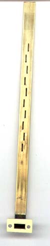
5. The resultant antenna can be seen in the picture fitted to a home made bend and flange - ready to bolt straight on to the PA. At this stage the end stop and matching screws had yet to be fitted.
6. Tests carried out recently (oct 2006) have shown that the peak of the output pattern at 24048MHz is clearly at right angles to the antenna axis with no dishing. The actual angle of spread has yet to be measured.
SLOTANT PROGRAM
CALCULATES SLOT DIMENSIONS FOR WAVEGUIDE ANTENNAS
K&S 268
BASED ON ARTICLE BY STEPHEN BELL KB7TRZ IN 1995 WEST COAST VHF/UHF
CONFERENCE PROCEEDINGS.
ENTER NUMBER OF SLOTS DESIRED ? 10
ENTER INTERNAL WIDE DIMENSION OF WAVEGUIDE IN INCHES ? 0.336
ENTER INTERNAL NARROW DIMENSION OF W.G. IN INCHES ? 0.162
ENTER DESIRED OPERATING FREQUENCY IN MHZ ? 24192
W.G. CUTOFF WAVELENGTH IS 17.06 MM
W.G. CUTOFF FREQUENCY IS 17575.93 MHz
FREE SPACE WAVELENGTH IS 12.40 MM
GUIDE WAVELENGTH IS 18.04 MM OR .710 IN.
SLOT OFFSET FROM CENTERLINE IS .72 MM OR 0.028 IN.
SLOT LENGTH IS 6.20 MM OR .244 IN.
SLOT VERT. CNTR-CNTR SPACING IS 9.02 MM OR .355 IN.
APPROX SLOT WIDTH IS .90 MM OR 0.035 IN.
WAVEGUIDE END PLATE SHOULD BE AN ODD MULTIPLE OF 4.51 MM OR .177 INCHES FROM END OF TOP SLOT.
 E-Mail: davidwrigley@microwave.fsnet.co.uk
Last updated 2006 Oct 29